
[Solved]Learned Analyse Behavior Asynchronous Counter Used Sb74293 Depicted Page 456 Figure 714 Co Q37035123
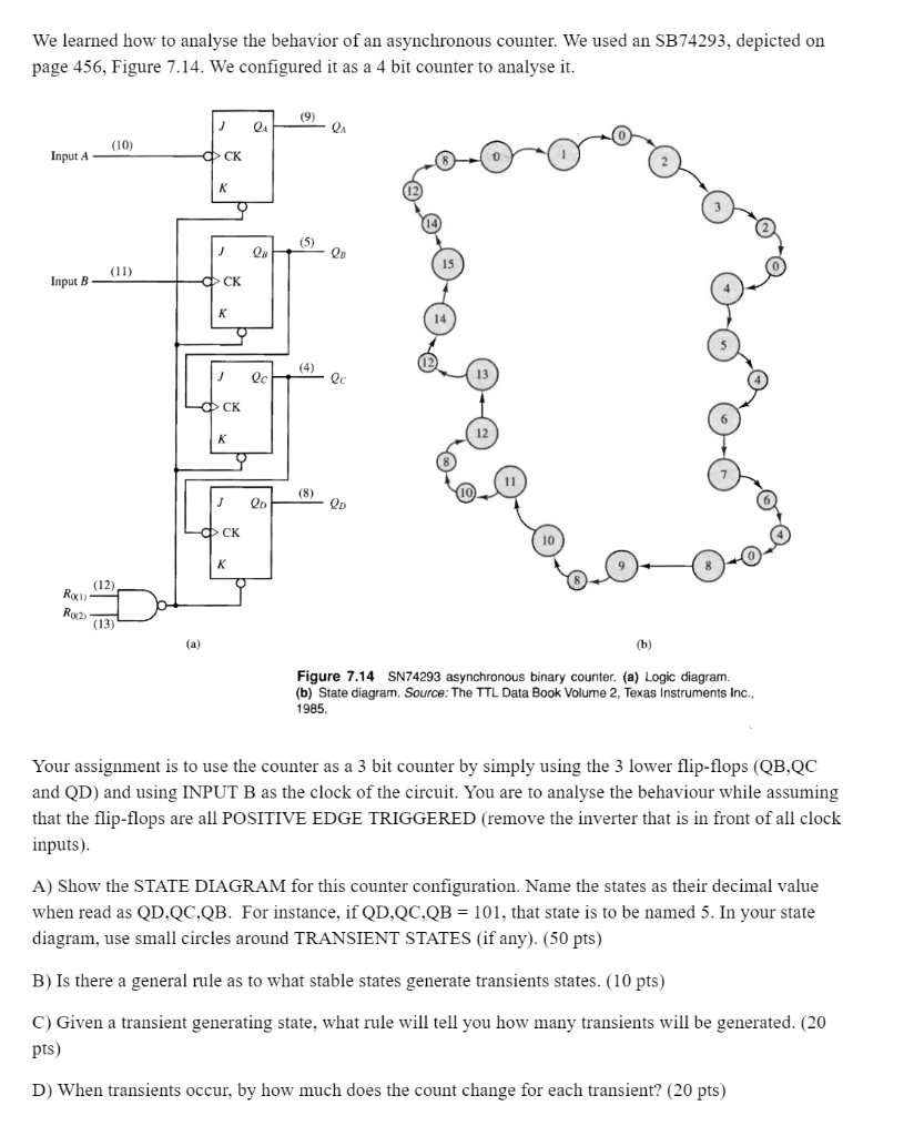
We learned how to analyse the behavior of an asynchronous counter. We used an SB74293, depicted on page 456, Figure 7.14. We configured it as a 4 bit counter to analyse it (10) Input A CK 15 Input B CK 13 CK 12 J Qo QD CK 10 (12) xi) 0x2) (13) Figure 7.14 SN74293 asynchronous binary counter. (a) Logic diagram (b) State diagram. Sorce: The TTL Data Book Volume 2, Texas Instruments Inc., 1985 Your assignment is to use the counter as a 3 bit counter by simply using the 3 lower flip-flops (QB,QC and QD) and using INPUT B as the clock of the circuit. You are to analyse the behaviour while assuming that the flip-flops are all POSITIVE EDGE TRIGGERED (remove the inverter that is in front of all clock inputs) A) Show the STATE DIAGRAM for this counter configuration. Name the states as their decimal value when read as QD,QC,QB. For instance, if QD,QC,QB-101, that state is to be named 5. In your state diagram, use small circles around TRANSIENT STATES (if any). (50 pts) B) Is there a general rule as to what stable states generate transients states. (10 pts) C) Given a transient generating state, what rule will tell you how many transients will be generated. (20 pts) D) When transients occur, by how much does the count change for each transient? (20 pts) Show transcribed image text We learned how to analyse the behavior of an asynchronous counter. We used an SB74293, depicted on page 456, Figure 7.14. We configured it as a 4 bit counter to analyse it (10) Input A CK 15 Input B CK 13 CK 12 J Qo QD CK 10 (12) xi) 0x2) (13) Figure 7.14 SN74293 asynchronous binary counter. (a) Logic diagram (b) State diagram. Sorce: The TTL Data Book Volume 2, Texas Instruments Inc., 1985 Your assignment is to use the counter as a 3 bit counter by simply using the 3 lower flip-flops (QB,QC and QD) and using INPUT B as the clock of the circuit. You are to analyse the behaviour while assuming that the flip-flops are all POSITIVE EDGE TRIGGERED (remove the inverter that is in front of all clock inputs) A) Show the STATE DIAGRAM for this counter configuration. Name the states as their decimal value when read as QD,QC,QB. For instance, if QD,QC,QB-101, that state is to be named 5. In your state diagram, use small circles around TRANSIENT STATES (if any). (50 pts) B) Is there a general rule as to what stable states generate transients states. (10 pts) C) Given a transient generating state, what rule will tell you how many transients will be generated. (20 pts) D) When transients occur, by how much does the count change for each transient? (20 pts)
Expert Answer
Answer to We learned how to analyse the behavior of an asynchronous counter. We used an SB74293, depicted on page 456, Figure 7.14… . . .
OR
