
[Solved]Jects 201902 Engg 030 Engg C Https Learn Us East 1 Prod Fleet01 Xythoss3 Engg 30 Spring 20 Q37287360
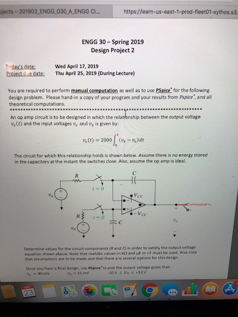
jects-201902 ENGG 030 A ENGG C… https://learn-us-east-1-prod-fleet01-xythos.s3 ENGG 30-Spring 2019 Design Project 2 Today’s date: Proiect due date: Wed April 17, 2019 Thu April 25, 2019 (During Lecture) You are required to perform manual computation as well as to use PSpice for the following design problem. Please hand-in a copy of your program and your results from Pspice’, and all theoretical computations An op amp circuit is to be designed in which the relatonship between the output voltage vo (t) and the input voltages va and v, is given by: o(t) 2000 Va)dt The circuit for which this relationship holds is shown below. Assume there is no energy stored in the capacitors at the instant the switches close. Also, assume the op amp is ideal. e, Determine values for the circuit components (R and C) in order to satisfy the output voltage equation shown above. Note that realistic values in kΩ and μF or nF must be used. Also note that assumptions are to be made and that there are several options for this design Once you have a final design, use PSpice’ to plot the output veltage given that 40 mV 23 Show transcribed image text jects-201902 ENGG 030 A ENGG C… https://learn-us-east-1-prod-fleet01-xythos.s3 ENGG 30-Spring 2019 Design Project 2 Today’s date: Proiect due date: Wed April 17, 2019 Thu April 25, 2019 (During Lecture) You are required to perform manual computation as well as to use PSpice for the following design problem. Please hand-in a copy of your program and your results from Pspice’, and all theoretical computations An op amp circuit is to be designed in which the relatonship between the output voltage vo (t) and the input voltages va and v, is given by: o(t) 2000 Va)dt The circuit for which this relationship holds is shown below. Assume there is no energy stored in the capacitors at the instant the switches close. Also, assume the op amp is ideal. e, Determine values for the circuit components (R and C) in order to satisfy the output voltage equation shown above. Note that realistic values in kΩ and μF or nF must be used. Also note that assumptions are to be made and that there are several options for this design Once you have a final design, use PSpice’ to plot the output veltage given that 40 mV 23
Expert Answer
Answer to jects-201902 ENGG 030 A ENGG C… https://learn-us-east-1-prod-fleet01-xythos.s3 ENGG 30-Spring 2019 Design Project 2 To… . . .
OR
