
[Solved]Given Antenna Azimuth Position Control System Shown Antenna Desired Azimuth Angle Input Az Q37092869
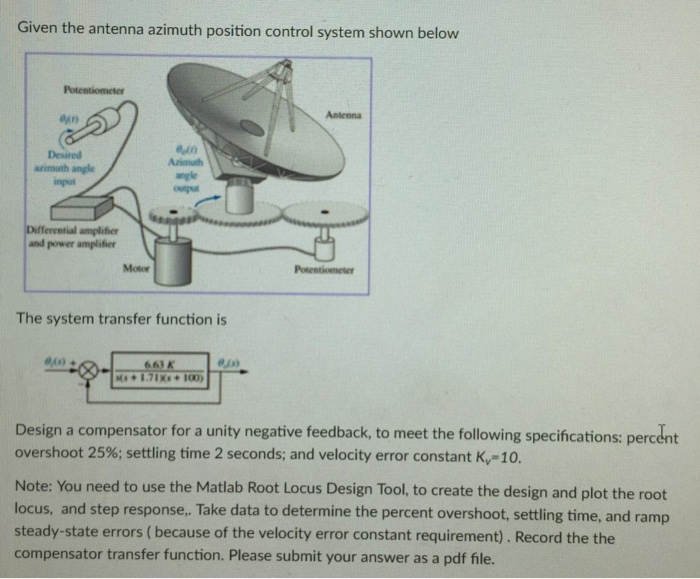 6.63k/s(s+1.7)(s+100)Given the antenna azimuth position control system shown below Antenna Desired azimuth angle input Azimuth angle Differential amplifier and power amplifier Motor The system transfer function is 66K Design a compensator for a unity negative feedback, to meet the following specifications: percent overshoot 25%; settling time 2 seconds; and velocity error constant K,-10. Note: You need to use the Matlab Root Locus Design Tool, to create the design and plot the root locus, and step response,. Take data to determine the percent overshoot, settling time, and ramp steady-state errors ( because of the velocity error constant requirement). Record the the compensator transfer function. Please submit your answer as a pdf file. Show transcribed image text Given the antenna azimuth position control system shown below Antenna Desired azimuth angle input Azimuth angle Differential amplifier and power amplifier Motor The system transfer function is 66K Design a compensator for a unity negative feedback, to meet the following specifications: percent overshoot 25%; settling time 2 seconds; and velocity error constant K,-10. Note: You need to use the Matlab Root Locus Design Tool, to create the design and plot the root locus, and step response,. Take data to determine the percent overshoot, settling time, and ramp steady-state errors ( because of the velocity error constant requirement). Record the the compensator transfer function. Please submit your answer as a pdf file.
Expert Answer
Answer to Given the antenna azimuth position control system shown below Antenna Desired azimuth angle input Azimuth angle Differen… . . .
OR
