
[Solved]Design Sequential Circuits Exercise 10 Design Sequential Circuit Illustrated Figure 11 Seq Q37255821
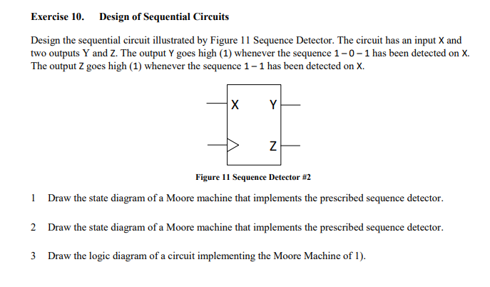
Design of Sequential Circuits Exercise 10. Design the sequential circuit illustrated by Figure 11 Sequence Detector. The circuit has an input X and two outputs Y and Z. The output Y goes high (1) whenever the sequence 1-0-1 has been detected on X. The output Z goes high (1) whenever the sequence 1 – 1 has been detected on X. Figure 1 Sequence Detector #2 Draw the state diagram of a Moore machine that implements the prescribed sequence detector. Draw the state diagram of a Moore machine that implements the prescribed sequence detector. Draw the logic diagram of a circuit implementing the Moore Machine of 1). 1 2 3 Show transcribed image text Design of Sequential Circuits Exercise 10. Design the sequential circuit illustrated by Figure 11 Sequence Detector. The circuit has an input X and two outputs Y and Z. The output Y goes high (1) whenever the sequence 1-0-1 has been detected on X. The output Z goes high (1) whenever the sequence 1 – 1 has been detected on X. Figure 1 Sequence Detector #2 Draw the state diagram of a Moore machine that implements the prescribed sequence detector. Draw the state diagram of a Moore machine that implements the prescribed sequence detector. Draw the logic diagram of a circuit implementing the Moore Machine of 1). 1 2 3
Expert Answer
Answer to Design of Sequential Circuits Exercise 10. Design the sequential circuit illustrated by Figure 11 Sequence Detector. The… . . .
OR
