
[Solved]57 Hardware Description Language Models Examples 59 510 Present Hdl Models Mealy Moore Fs Q37248022
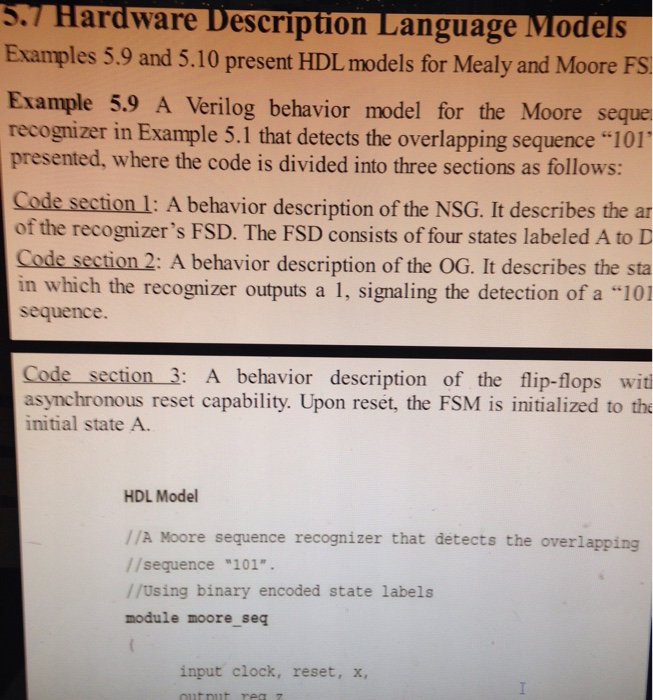
 5.7 Hardware Description Language Models Examples 5.9 and 5.10 present HDL models for Mealy and Moore FS Example 5.9 A Verilog behavior model for the Moore seque recognizer in Example 5.1 that detects the overlapping sequence “101 presented, where the code is divided into three sections as follows: Code section 1: A behavior description of the NSG. It describes the ar of the recognizer’s FSD. The FSD consists of four states labeled A to D Code section 2: A behavior description of the OG. It describes the sta in which the recognizer outputs a 1, signaling the detection of a “101 sequence Code section 3: A behavior description of the flip-flops wit asynchronous reset capability. Upon reset, the FSM is initialized to th initial state A. HDL Model //A Moore sequence recognizer that detects the overlapping //sequence “101 //Using binary encoded state labels module moore seq input clock, reset, x, output reg 7 HDL Model //A Moore sequence recognizer that detects the overlapping //sequence 101”. //Using binary encoded state labels module moore seq input clock, reset, x output reg z ) i //assign binary encoded codes to the states A through D parameter A 2’boo, 2,b10, С reg [1:0] current state, next_state; //Section 1: Next state generator (NSG) alwayse( begin casex (current state) //ignore unknown and high //impedance (2) inputs next state= B; else next state = A; if (x=1) B: nextstate B; – else nextstate = c; – if (x=1) C: next-state = D; next_stateA next-state B; next state = c; else if (x=1) D: else endcase end //Section 2: Output generator (oG) always@(*) begin if (currentstate = D) – z=1; else z=0; end / /Sections 3: The flip-flops alwaysa (posedge clock, posedge reset) begin it (reset 1) curzent state A else current state next_state end endmodule Simulation Test-Bench include “moore_seq.v module tester ); reg clock, reset, x wire z; moore_seq ul(clock, reset, x, z) initial begin smonitor(14d: z b, $time, z) clock = 0; reset 1; //reset the flip-flops #10 reset: 0; //end reset l end always We were unable to transcribe this imageChronologic VCS siaulator copyright 1991-2999 Contains Synopays proprietary informat io Compiler version D-2009,12j Runtine vereion 0-2999 32 01 10:x#1 201 x= 1 30: x1 501 x # 1 601 x = 0 70; x = 1 853 100: x=0 stinish called froml file “tester.v, line 32 Sfinish at simulation tine 110 pio Sot sequence A recognizer can be designed to recognize either an overlapping or nonoverlapping sequence. For example, the input sequence “10101” contains two overlapping sequences of 101,” where the “1” in the center of the input sequence is shared. On the other hand, there are two nonoverlapping “101 sequences in the input sequence “101101.” 64199 Example 5.1 The design of a Moore FSM that detects the overlapping sequence “101”: Solution Figure 5.13 shows the top-level bbck dagram of the sequence recognizer with the external input x and the output :. Its Moore FSD is also shown with four states labeled A, B, C and D. The active-high reset signal ธ used to asynchronous initialize the machine to a known state A, as ilustrated by an arrow labeled reset in the FSD. An input sequence is processed one bit at a time. The recognizer makes a transition to a new state each time that it counters the next bit in the target sequence. For example, if the recognizer is in the state C, it indicates that it has received the first 2-bits of the target sequence. The output : is shown beow each state and becomes I when the recognizer receives the last bit of the target sequence and enters state D. The : is 0 in all other states. The recognizer woukd reject all other 3-bit sequences that it inputs and start over each time The detais of alternative solutions are discussed next. -11010101 101 11-х. Oerlapping .101. Sequence Recognize z-0 1101010110111 x-0 ←reset z-0 I 0 I ” sequence recognizer and its FİGU R E 5.1 3 A block diagram of a Moore FSD Part 1) Implement the Moore FSM sequencer of example 5.9 (section 5.7 of textbook) and implement the same test bench. a) Submit a screen shot of this simulation. Part 2) Redesign the Moore FSM to detect the sequence “110 and simulate using the same testbench of examplie 5.9 Submit the following: a) Moore Transition Diagram for the new sequence 110. b) The modified verilog module c) printscreen of the new simulation Show transcribed image text 5.7 Hardware Description Language Models Examples 5.9 and 5.10 present HDL models for Mealy and Moore FS Example 5.9 A Verilog behavior model for the Moore seque recognizer in Example 5.1 that detects the overlapping sequence “101 presented, where the code is divided into three sections as follows: Code section 1: A behavior description of the NSG. It describes the ar of the recognizer’s FSD. The FSD consists of four states labeled A to D Code section 2: A behavior description of the OG. It describes the sta in which the recognizer outputs a 1, signaling the detection of a “101 sequence Code section 3: A behavior description of the flip-flops wit asynchronous reset capability. Upon reset, the FSM is initialized to th initial state A. HDL Model //A Moore sequence recognizer that detects the overlapping //sequence “101 //Using binary encoded state labels module moore seq input clock, reset, x, output reg 7
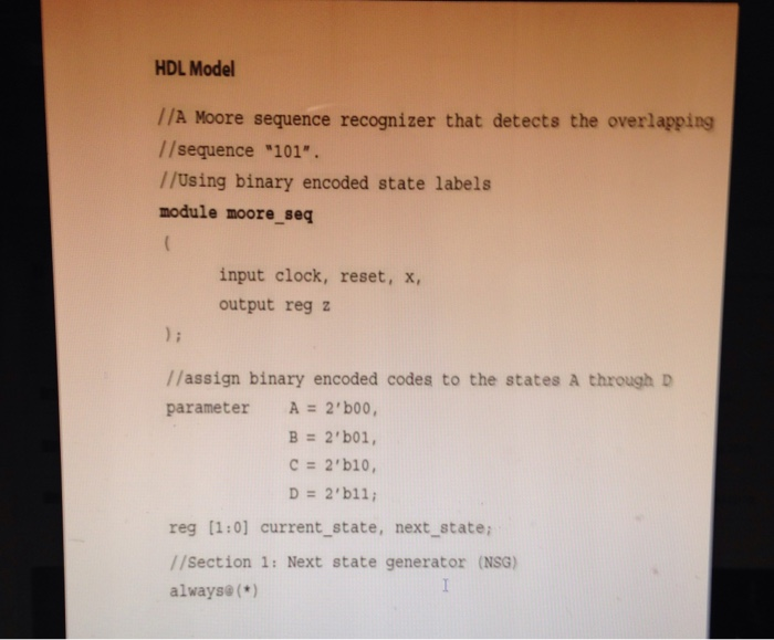
HDL Model //A Moore sequence recognizer that detects the overlapping //sequence 101″. //Using binary encoded state labels module moore seq input clock, reset, x output reg z ) i //assign binary encoded codes to the states A through D parameter A 2’boo, 2,b10, С reg [1:0] current state, next_state; //Section 1: Next state generator (NSG) alwayse(
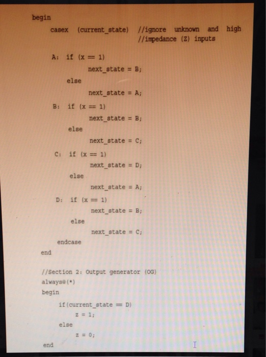
begin casex (current state) //ignore unknown and high //impedance (2) inputs next state= B; else next state = A; if (x=1) B: nextstate B; – else nextstate = c; – if (x=1) C: next-state = D; next_stateA next-state B; next state = c; else if (x=1) D: else endcase end //Section 2: Output generator (oG) always@(*) begin if (currentstate = D) – z=1; else z=0; end
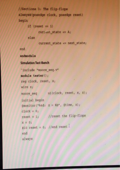
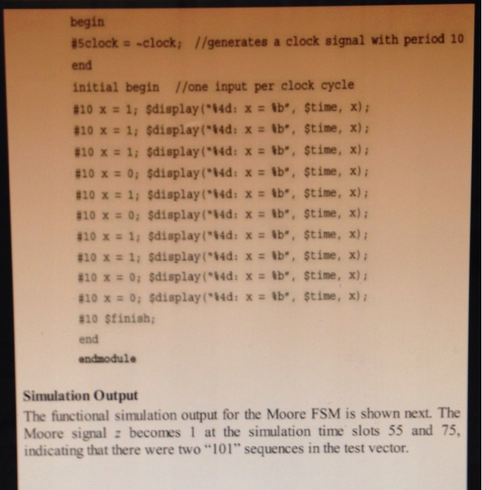
/ /Sections 3: The flip-flops alwaysa (posedge clock, posedge reset) begin it (reset 1) curzent state A else current state next_state end endmodule Simulation Test-Bench include “moore_seq.v module tester ); reg clock, reset, x wire z; moore_seq ul(clock, reset, x, z) initial begin smonitor(14d: z b, $time, z) clock = 0; reset 1; //reset the flip-flops #10 reset: 0; //end reset l end always
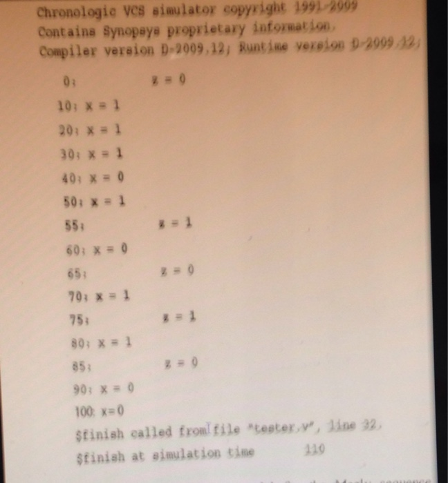
Chronologic VCS siaulator copyright 1991-2999 Contains Synopays proprietary informat io Compiler version D-2009,12j Runtine vereion 0-2999 32 01 10:x#1 201 x= 1 30: x1 501 x # 1 601 x = 0 70; x = 1 853 100: x=0 stinish called froml file “tester.v, line 32 Sfinish at simulation tine 110
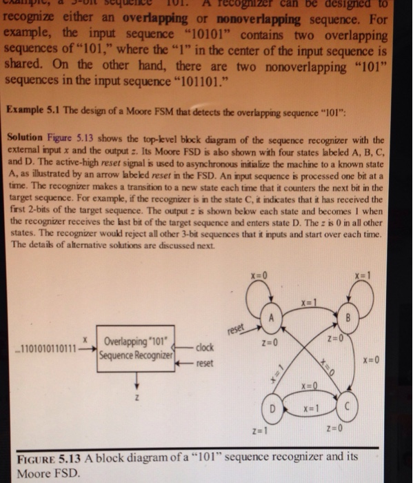
pio Sot sequence A recognizer can be designed to recognize either an overlapping or nonoverlapping sequence. For example, the input sequence “10101” contains two overlapping sequences of 101,” where the “1” in the center of the input sequence is shared. On the other hand, there are two nonoverlapping “101 sequences in the input sequence “101101.” 64199 Example 5.1 The design of a Moore FSM that detects the overlapping sequence “101”: Solution Figure 5.13 shows the top-level bbck dagram of the sequence recognizer with the external input x and the output :. Its Moore FSD is also shown with four states labeled A, B, C and D. The active-high reset signal ธ used to asynchronous initialize the machine to a known state A, as ilustrated by an arrow labeled reset in the FSD. An input sequence is processed one bit at a time. The recognizer makes a transition to a new state each time that it counters the next bit in the target sequence. For example, if the recognizer is in the state C, it indicates that it has received the first 2-bits of the target sequence. The output : is shown beow each state and becomes I when the recognizer receives the last bit of the target sequence and enters state D. The : is 0 in all other states. The recognizer woukd reject all other 3-bit sequences that it inputs and start over each time The detais of alternative solutions are discussed next. -11010101 101 11-х. Oerlapping .101. Sequence Recognize z-0 1101010110111 x-0 ←reset z-0 I 0 I ” sequence recognizer and its FİGU R E 5.1 3 A block diagram of a Moore FSD
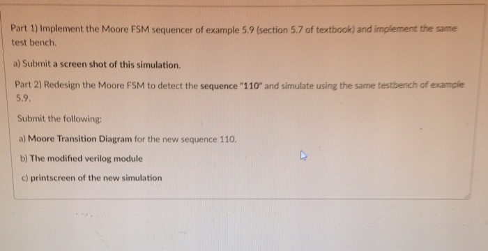
Part 1) Implement the Moore FSM sequencer of example 5.9 (section 5.7 of textbook) and implement the same test bench. a) Submit a screen shot of this simulation. Part 2) Redesign the Moore FSM to detect the sequence “110 and simulate using the same testbench of examplie 5.9 Submit the following: a) Moore Transition Diagram for the new sequence 110. b) The modified verilog module c) printscreen of the new simulation
Expert Answer
Answer to 5.7 Hardware Description Language Models Examples 5.9 and 5.10 present HDL models for Mealy and Moore FS Example 5.9 A V… . . .
OR
