
[Solved]Design Serial Adder Jk Flip Flop Draw Corresponding Logic Circuit Two Binary Numbers Added Q37290885
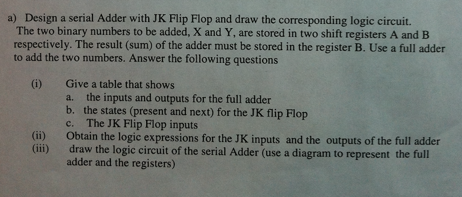
Design a serial Adder with JK Flip Flop and draw the corresponding logic circuit. The two binary numbers to be added, X and Y, are stored in two shift registers A and B respectively. The result (sum) of the adder must be stored in the register B. Use a full adder to add the two numbers. Answer the following questions a) Give a table that shows a. the inputs and outputs for the full adder b. the states (present and next) for the JK flip Flop c. The JK Flip Flop inputs Obtain the logic expressions for the JK inputs and the outputs of the full adder draw the logic circuit of the serial Adder (use a diagram to represent the full adder and the registers) (i) (ii) (iii) Show transcribed image text Design a serial Adder with JK Flip Flop and draw the corresponding logic circuit. The two binary numbers to be added, X and Y, are stored in two shift registers A and B respectively. The result (sum) of the adder must be stored in the register B. Use a full adder to add the two numbers. Answer the following questions a) Give a table that shows a. the inputs and outputs for the full adder b. the states (present and next) for the JK flip Flop c. The JK Flip Flop inputs Obtain the logic expressions for the JK inputs and the outputs of the full adder draw the logic circuit of the serial Adder (use a diagram to represent the full adder and the registers) (i) (ii) (iii)
Expert Answer
Answer to Design a serial Adder with JK Flip Flop and draw the corresponding logic circuit. The two binary numbers to be added, X … . . .
OR
