
[Solved]Write Vhdl Code Controller B Write Test Bench C Write Ucf File Use State Diagram Q37290349
A. Write a VHDL Code for the Controller
B. Write a Test Bench
C. Write a UCF File
Use this State Diagram
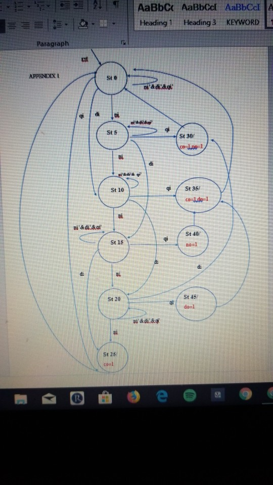
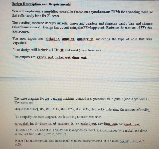
Design Description and Requirements You will implement a simplified controller (based on a synchronous FSM) for a vending machine that sells candy bars for 25 cents. The vending machine accepts nickels, dimes and quarters and dispense candy bars and change (nickels and dimes). Design this circuit using the FSM approach Estimate the mumber of FFs that are required The user inputs are: nickelin, dime见quarter.黒indicating the type of coin that was deposited Your design will include a 1 Hz cll and reset (asynchronous). The outputs are: candy..out, nickelout, dime out The state diagram for the xending machine controller is presented in Figure 1 (and Appendix 1). The states are: stO (initial state), st5, st10, st15, st20, st25, st30, st35, st40, st45 (indicating the amount of credit) To simplify the state diagram, the following notation was used: ni-nickel in. di-dime in. qi-quarter in, no-nickel out, do-dime out, co-candy-Out. In states s25, s30 and st35 a candy bar is dispensed (co#1), accompanied by a nickel and dime in the last two states (no=,1′, do= Note: The machine will stay in state sto, if no coins are inserted. It is similar for st5, st10, st15, st20
Expert Answer
Answer to A. Write a VHDL Code for the Controller B. Write a Test Bench C. Write a UCF File Use this State Diagram … . . .
OR
