
[Solved]4 Bit Controlled Comparator Specifications Inputs Create Circuit Logisim Take Following In Q37212434
follow each specifications listed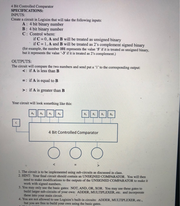 4 Bit Controlled Comparator SPECIFICATIONS: INPUTS: Create a circuit in Logisim that will take the following inputs: A: 4 bit binary number B: 4 bit binary number C: Control where: if C if C 0, A and B will be treated as unsigned binary 1, A and B will be treated as 2’s complement signed binary (for example, the number 101 represents the value 5′ if it is treated as unsigned binary, but it represents the value -3′ if it is treated as 2’s complement.) OUTPUTS: The circuit will compare the two numbers and send put a ‘l’to the corresponding output: <. if A is less than B : if A is equal to B >: if A is greater than EB Your circuit will look something like this 4 Bit Controlled Comparator ООО 1. The circuit is to be implemented using sub-circuits as discussed in class. 2. HINT: Your final circuit should contain an UNSIGNED COMPARATOR. You will then need to make modifications to the outputs of the UNSIGNED COMPARATOR to make it work with signed numbers. 3. You may only use the basic gates: NOT, AND, OR, XOR. You may use these gates to build larger sub-circuits of your own: ADDER, MULTIPLEXER, etc. and incorporate these into your main circuit. 4. You are not allowed to use Logisim’s built-in circuits: ADDER, MULTIPLEXER, etc., but you are free to build your own using the basic gates. Show transcribed image text 4 Bit Controlled Comparator SPECIFICATIONS: INPUTS: Create a circuit in Logisim that will take the following inputs: A: 4 bit binary number B: 4 bit binary number C: Control where: if C if C 0, A and B will be treated as unsigned binary 1, A and B will be treated as 2’s complement signed binary (for example, the number 101 represents the value 5′ if it is treated as unsigned binary, but it represents the value -3’ if it is treated as 2’s complement.) OUTPUTS: The circuit will compare the two numbers and send put a ‘l’to the corresponding output: : if A is greater than EB Your circuit will look something like this 4 Bit Controlled Comparator ООО 1. The circuit is to be implemented using sub-circuits as discussed in class. 2. HINT: Your final circuit should contain an UNSIGNED COMPARATOR. You will then need to make modifications to the outputs of the UNSIGNED COMPARATOR to make it work with signed numbers. 3. You may only use the basic gates: NOT, AND, OR, XOR. You may use these gates to build larger sub-circuits of your own: ADDER, MULTIPLEXER, etc. and incorporate these into your main circuit. 4. You are not allowed to use Logisim’s built-in circuits: ADDER, MULTIPLEXER, etc., but you are free to build your own using the basic gates.
Expert Answer
Answer to 4 Bit Controlled Comparator SPECIFICATIONS: INPUTS: Create a circuit in Logisim that will take the following inputs: A: … . . .
OR
