
[solved]-Title System Verilog Code 32 Bit Alu System Functions 4 Operations Add Sub Orr 4 Bits Aluf Q39073020
Title: System Verilog Code for a 32-bit ALU System
Functions: 4 operations: ADD, SUB, AND, ORR with 4 bits ofALUFlags: Negative, Zero, Carryout, Overflow
Our questions: Hi, after doing some research, we are stillstruggling on how to implement the Carryout Flag and Overflow Flag.We comment out the code as shown below. Can you please help.
Detail Instructions: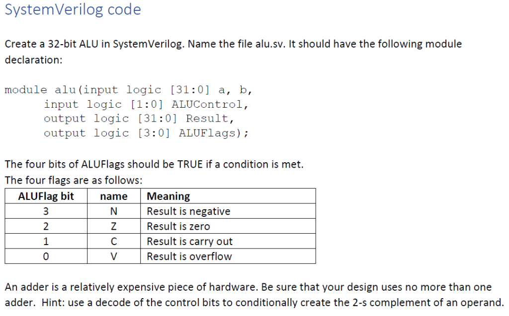
Our Code:![Emodule alu(input logic (31:0] a, b, input logic [1:0] ALUControl, output logic (31:01 Result, output logic (3:0] ALUFlags);](https://media.cheggcdn.com/media/ff8/s678x586/ff847cc3-0879-4015-a044-b32f1698cb31/phpp3CrIp.png)
![30 32 // Negative Flag ALUFlags [3] = (Result[31]) ? 1:0; 33 end 35 36 endmodule](https://media.cheggcdn.com/media/9db/s682x149/9dbc2005-212a-415f-8ebd-3105dcb2bede/phpZwQX2Z.png)
SystemVerilog code Create a 32-bit ALU in System Verilog. Name the file alu.sv. It should have the following module declaration: module alu (input logic (31:0] a, b, input logic (1:0] ALUControl, output logic (31:0] Result, output logic (3:0] ALUFlags); The four bits of ALUFlags should be TRUE if a condition is met. The four flags are as follows: ALUFlag bit name Meaning N. Result is negative Z Result is zero с Result is carry out Result is overflow An adder is a relatively expensive piece of hardware. Be sure that your design uses no more than one adder. Hint: use a decode of the control bits to conditionally create the 2-s complement of an operand. Control inputs There are a large number of possible control inputs on a complete ARM ALU. For this example, we will start smaller. The four operations will be: Op Code Operation ADD SUB AND ORR ALU Control bits 00 01 10 11 Status effects N, Z, C, V N, Z, C, V N. Z N. Z | Add operands A and B (A+B), with carry out Subtract operands A and B (A-B), with borrow (~C) out Logical AND of A and B (A&B) Logical OR of A and B (AIB) Emodule alu(input logic (31:0] a, b, input logic [1:0] ALUControl, output logic (31:01 Result, output logic (3:0] ALUFlags); reg [32:0] Carry; always_comb Ebegin Ecase (ALUControl) 2’boo: {Result, carry} = a + b; // Addition // Overflow Flag //ALUFlags [0] = (-(a[31]Ab [31]) Aresult[31]) ? 1:0; // Carry Out Flag //ALUFlags [1] = (Carry[32] == 1) ? 1:0; 2’b01: Result = a – b; // subtraction // Overflow Flag //ALUFlags [0] = (-(a[31]Ab [31]) Result[31]) ? 1:0; // Carry Out Flag //ALUFlags [1] = (Carry[32] == 1) ? 1:0; 2’b10: Result = a & b; // AND 2’b11: Result = a / b; // OR endcase // Zero Flag ALUFlags [2] = (Result == 32’60) ? 1:0; 30 32 // Negative Flag ALUFlags [3] = (Result[31]) ? 1:0; 33 end 35 36 endmodule Show transcribed image text SystemVerilog code Create a 32-bit ALU in System Verilog. Name the file alu.sv. It should have the following module declaration: module alu (input logic (31:0] a, b, input logic (1:0] ALUControl, output logic (31:0] Result, output logic (3:0] ALUFlags); The four bits of ALUFlags should be TRUE if a condition is met. The four flags are as follows: ALUFlag bit name Meaning N. Result is negative Z Result is zero с Result is carry out Result is overflow An adder is a relatively expensive piece of hardware. Be sure that your design uses no more than one adder. Hint: use a decode of the control bits to conditionally create the 2-s complement of an operand.
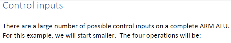
Control inputs There are a large number of possible control inputs on a complete ARM ALU. For this example, we will start smaller. The four operations will be:
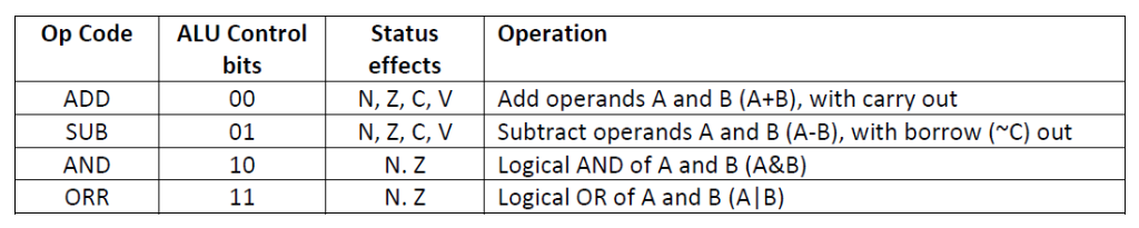
Op Code Operation ADD SUB AND ORR ALU Control bits 00 01 10 11 Status effects N, Z, C, V N, Z, C, V N. Z N. Z | Add operands A and B (A+B), with carry out Subtract operands A and B (A-B), with borrow (~C) out Logical AND of A and B (A&B) Logical OR of A and B (AIB)
Emodule alu(input logic (31:0] a, b, input logic [1:0] ALUControl, output logic (31:01 Result, output logic (3:0] ALUFlags); reg [32:0] Carry; always_comb Ebegin Ecase (ALUControl) 2’boo: {Result, carry} = a + b; // Addition // Overflow Flag //ALUFlags [0] = (-(a[31]Ab [31]) Aresult[31]) ? 1:0; // Carry Out Flag //ALUFlags [1] = (Carry[32] == 1) ? 1:0; 2’b01: Result = a – b; // subtraction // Overflow Flag //ALUFlags [0] = (-(a[31]Ab [31]) Result[31]) ? 1:0; // Carry Out Flag //ALUFlags [1] = (Carry[32] == 1) ? 1:0; 2’b10: Result = a & b; // AND 2’b11: Result = a / b; // OR endcase // Zero Flag ALUFlags [2] = (Result == 32’60) ? 1:0;
30 32 // Negative Flag ALUFlags [3] = (Result[31]) ? 1:0; 33 end 35 36 endmodule
Expert Answer
Answer to Title: System Verilog Code for a 32-bit ALU System Functions: 4 operations: ADD, SUB, AND, ORR with 4 bits of ALUFlags: … . . .
OR
