
[Solved]Task Connect Button Arduino Two Leds One Led Stay Whenever Button Pressed Turn Pressed But Q37245577
what do i need to change in my code for my hardware tooperate?
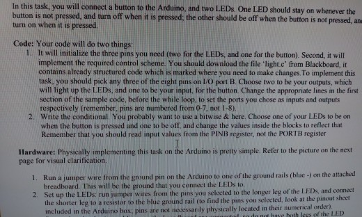
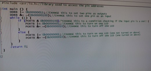
In this task, you will connect a button to the Arduino, and two LEDs. One LED should stay on whenever the button is not pressed, and turn off when it is pressed: the other should be off when the button is not pressed, an turn on when it is pressed Code: Your code will do two things 1. It will initialize the three pins you need (two for the LEDs, and one for the button). Second, it will implement the required control scheme. You should download the file ‘light.c’ from Blackboard, it contains already structured code which is marked where you need to make changes. To implement this task, you should pick any three of the eight pins on L/O port B. Choose two to be your outputs, which will light up the LEDs, and one to be your input, for the button Change the appropriate lines in the first section of the sample code, before the while loop, to set the ports you chose as inputs and outputs respectively (remember, pins are numbered from 0-7, not 1-8) Write the conditional. You probably want to use a bitwise & here. Choose one of your LEDs to be on when the button is pressed and one to be off, and change the values inside the blocks to reflect that. Remember that you should read input values from the PINB register, not the PORTB register 2. Hardware: Physically implementing this task on the Arduino is preny simple Refer to the picture on the nex 1. Run a jumper wire ftom the ground pin on the Arduino to one of the ground rails (blue -) on the attached 2. Set up the LEDs.: run jumper wires from the pins you selected to the longer leg of the LEDs, and connect page for visual clarification breadboard. This will be the ground that you connect the LEDs to the shorter leg to a resistor to the blue ground rail (to find the pins you selected, look at the pinout sheet included ihysically.located in their numerical order) in the Arduino box; pins are not necessarily do not have both legs of the LED #include <av r/1o.ro//norary used to access the pinaireses int main O t DDRBに0b00000011; //CHANGE DDRB Cobo0000100D/CHANGE this to set one pin as an irout this to set two pins as outputs while (1) if PORTB & oboooooro0D/ CHANGE this to a condit ion checking if the ingut pin is a one PORTB 0b00000001;CHANGE this to turn on one LED PORTB &Cob00000010):/CHANGE this to turn off one LED 1: ICHANGE this to turn on one LED (one not turned on above) 010)A/CHANGE this to turn off one LED Cone turned on above) else f 001; PORTB return o: Show transcribed image text In this task, you will connect a button to the Arduino, and two LEDs. One LED should stay on whenever the button is not pressed, and turn off when it is pressed: the other should be off when the button is not pressed, an turn on when it is pressed Code: Your code will do two things 1. It will initialize the three pins you need (two for the LEDs, and one for the button). Second, it will implement the required control scheme. You should download the file ‘light.c’ from Blackboard, it contains already structured code which is marked where you need to make changes. To implement this task, you should pick any three of the eight pins on L/O port B. Choose two to be your outputs, which will light up the LEDs, and one to be your input, for the button Change the appropriate lines in the first section of the sample code, before the while loop, to set the ports you chose as inputs and outputs respectively (remember, pins are numbered from 0-7, not 1-8) Write the conditional. You probably want to use a bitwise & here. Choose one of your LEDs to be on when the button is pressed and one to be off, and change the values inside the blocks to reflect that. Remember that you should read input values from the PINB register, not the PORTB register 2. Hardware: Physically implementing this task on the Arduino is preny simple Refer to the picture on the nex 1. Run a jumper wire ftom the ground pin on the Arduino to one of the ground rails (blue -) on the attached 2. Set up the LEDs.: run jumper wires from the pins you selected to the longer leg of the LEDs, and connect page for visual clarification breadboard. This will be the ground that you connect the LEDs to the shorter leg to a resistor to the blue ground rail (to find the pins you selected, look at the pinout sheet included ihysically.located in their numerical order) in the Arduino box; pins are not necessarily do not have both legs of the LED
#include
Expert Answer
Answer to what do i need to change in my code for my hardware to operate?… . . .
OR
