
[Solved]Missile System Figure 1 Aerodynamically Controlled Torque Created Deflection Control Surfa Q37067840
Please solve part Two of this question:
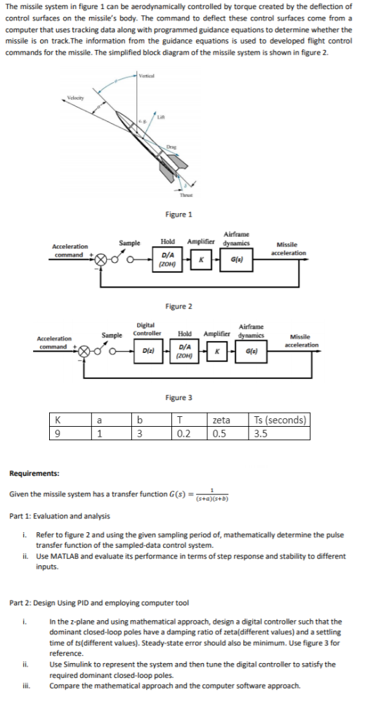
The missile system in figure 1 can be aerodynamically controlled by torque created by the deflection of control surfaces on the missile’s body. The command to deflect these control surfaces come from a computer that uses tracking data along with programmed guidance equations to determine whether the missile is on track.The information from the guidance equations is used to developed flight control commands for the missile. The simplified block diagram of the missile system is shown in figure 2 Figure 1 Hold Amplifier D/A Sample G(4) Figure 2 Amplifier dynamies Sample Controller Hold D/A Dz) G(s) Figure 3 zeta Ts (seconds) 3.5 9 0.2 0.5 Given the missile system has a transfer function G(s)- (s+a)(s+B) Part 1: Evaluation and analysis Refer to figure 2 and using the given sampling period of, mathematically determine the pulse transfer function of the sampled-data control system. i. ii. Use MATLAB and evaluate its performance in terms of step response and stability to different Part 2: Design Using PID and employing computer tool i. In the z-plane and using mathematical approach, design a digital controller such that the dominant closed-loop poles have a damping ratio of zeta(different values) and a settling time of ts(different values). Steady-state error should also be minimum. Use figure 3 for ii. Use Simulink to represent the system and then tune the digital controller to satisfy the required dominant closed-loop poles. Compare the mathematical approach and the computer software approach. ili. Show transcribed image text The missile system in figure 1 can be aerodynamically controlled by torque created by the deflection of control surfaces on the missile’s body. The command to deflect these control surfaces come from a computer that uses tracking data along with programmed guidance equations to determine whether the missile is on track.The information from the guidance equations is used to developed flight control commands for the missile. The simplified block diagram of the missile system is shown in figure 2 Figure 1 Hold Amplifier D/A Sample G(4) Figure 2 Amplifier dynamies Sample Controller Hold D/A Dz) G(s) Figure 3 zeta Ts (seconds) 3.5 9 0.2 0.5 Given the missile system has a transfer function G(s)- (s+a)(s+B) Part 1: Evaluation and analysis Refer to figure 2 and using the given sampling period of, mathematically determine the pulse transfer function of the sampled-data control system. i. ii. Use MATLAB and evaluate its performance in terms of step response and stability to different Part 2: Design Using PID and employing computer tool i. In the z-plane and using mathematical approach, design a digital controller such that the dominant closed-loop poles have a damping ratio of zeta(different values) and a settling time of ts(different values). Steady-state error should also be minimum. Use figure 3 for ii. Use Simulink to represent the system and then tune the digital controller to satisfy the required dominant closed-loop poles. Compare the mathematical approach and the computer software approach. ili.
Expert Answer
Answer to The missile system in figure 1 can be aerodynamically controlled by torque created by the deflection of control surfaces… . . .
OR
