
[Solved]Please Upload Screenshot Network Diagram Answer Steps Ve Completed Packet Tracer File Incl Q37125027
PLEASE UPLOAD A SCREENSHOT OF YOUR NETWORKDIAGRAM TO YOUR ANSWER WITH STEPS ON HOW YOU’VE COMPLETEDTHIS
- A packet tracer file that includes the following:
- Network Diagram that should have the following:
- Several computers per network. For example, you do not need toput 60 computers /network. Adding 2-3 computers per network shouldbe fine due to the limited space in packet Tracer.
- A Wireless Access Points per network. (You do not need toconfigure the AP for this course. This is done in Cisco II)
- Configurations:
- Configure IP addresses on computers & routers’ interfacesused in the diagram/internetwork. Do not forget to enable therouters’ interfaces after you configure them with IP addresses
- Configure the appropriate routing protocol on each router inthe interwork. Keep in mind when choosing the routingprotocol that the network in Figure 4-15 uses VLSM.
- After you are all done with configuration, make sure thatcomputers in one network can communicate (ping) with each other inthe same network as well as with computers on the othernetworks.
- Network Diagram that should have the following:
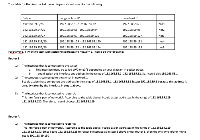
Your table for the cisco packet tracer diagram should look like the following Subnet 192.168.59 192.168.59.64/26 192.168.59.96/27 192.168.59.128/30 192.168.59.132/30 Range of host IP Broadcast IP 192.168.59.63 192.168.59.95 192.168.59.127 192.168.59.131 192.168.59.135 192.168.59.1 192.168.59.62 192.168.59.65 192.168.59.94 192.168.59.67 192.168.59.126 192.168.59.129 192.168.59.130 Neti net2 net3 net4 net5 192.168.59.133 192.168.59.134 Fgresamele, If I want to start with assigning addresses to network 1, I could do the following: Router B 1) The interface that is connected to the switch: a. This interface many be called g0/0 or g0/1 depending on your diagram in packet tracer. b. could assign this interface any address in the range of 192.168.59.1-192.168.59.62. So, I could pick 192.168.59.1 2) The computers connected to the switch in network 1 I could assign these computers any address in the range of 192.168.59.1 -192.168.59.62 Except 192.168.59.1 because this address is already taken by the interface in step 1 above. 3) The interface that is connected to router A: This interface is part of network4. According to the table above, I could assign addresses in the range of 192.168.59.129- 192.168.59.130. Therefore, I could choose 192.168.59.129 Router A: 1) The interface that is connected to router B: This interface is part of network4. According to the table above, I could assign addresses in the range of 192.168.59.129- 192.168.59.130. Since I gave 192.168.59.129 to router b interface as in step 3 above under router B, then the only one left for me to use is 192.168.59.130 192.168.59.0/24 192.168.59.0 /26 Net 1 Net 2 Net 3 Net 4 Net 5 Reserved 192.168.59.64 /26 192.168.59.64 /27 192.168.59.96 /27 192.168.59.128 /30 192.168.59.132 /30 192.168.59.136 through 192.168.59.128 /26 192.168.59.188 192.168.59.192 /26 Reserved Table 4-8 VLSM IP scheme for 192.168.59.0 Net 2 28 hosts Router A Net 4 2 hosts Net 5 2 hosts Router C Router B Net 1 60 hosts Net 3 10 hosts igure 4-15 Example internetwork for VISM Show transcribed image text Your table for the cisco packet tracer diagram should look like the following Subnet 192.168.59 192.168.59.64/26 192.168.59.96/27 192.168.59.128/30 192.168.59.132/30 Range of host IP Broadcast IP 192.168.59.63 192.168.59.95 192.168.59.127 192.168.59.131 192.168.59.135 192.168.59.1 192.168.59.62 192.168.59.65 192.168.59.94 192.168.59.67 192.168.59.126 192.168.59.129 192.168.59.130 Neti net2 net3 net4 net5 192.168.59.133 192.168.59.134 Fgresamele, If I want to start with assigning addresses to network 1, I could do the following: Router B 1) The interface that is connected to the switch: a. This interface many be called g0/0 or g0/1 depending on your diagram in packet tracer. b. could assign this interface any address in the range of 192.168.59.1-192.168.59.62. So, I could pick 192.168.59.1 2) The computers connected to the switch in network 1 I could assign these computers any address in the range of 192.168.59.1 -192.168.59.62 Except 192.168.59.1 because this address is already taken by the interface in step 1 above. 3) The interface that is connected to router A: This interface is part of network4. According to the table above, I could assign addresses in the range of 192.168.59.129- 192.168.59.130. Therefore, I could choose 192.168.59.129 Router A: 1) The interface that is connected to router B: This interface is part of network4. According to the table above, I could assign addresses in the range of 192.168.59.129- 192.168.59.130. Since I gave 192.168.59.129 to router b interface as in step 3 above under router B, then the only one left for me to use is 192.168.59.130
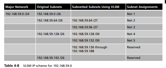
192.168.59.0/24 192.168.59.0 /26 Net 1 Net 2 Net 3 Net 4 Net 5 Reserved 192.168.59.64 /26 192.168.59.64 /27 192.168.59.96 /27 192.168.59.128 /30 192.168.59.132 /30 192.168.59.136 through 192.168.59.128 /26 192.168.59.188 192.168.59.192 /26 Reserved Table 4-8 VLSM IP scheme for 192.168.59.0
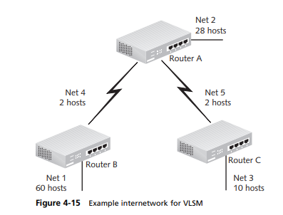
Net 2 28 hosts Router A Net 4 2 hosts Net 5 2 hosts Router C Router B Net 1 60 hosts Net 3 10 hosts igure 4-15 Example internetwork for VISM
Expert Answer
Answer to PLEASE UPLOAD A SCREENSHOT OF YOUR NETWORK DIAGRAM TO YOUR ANSWER WITH STEPS ON HOW YOU’VE COMPLETED THIS A packet trace… . . .
OR
