
[Solved]Design Digital Logic Circuit Using Logisim Using Minimal Amount Gates Realize Digital Look Q37242362
Design a digital logic circuit (USING LOGISIM), using minimalamount of gates that will realize a digital LookUp Table.
If you can do all steps that would be helpful, but moreimportantly I am looking for question d, ascreenshot of how it looks on logisim. If possible please do allsteps.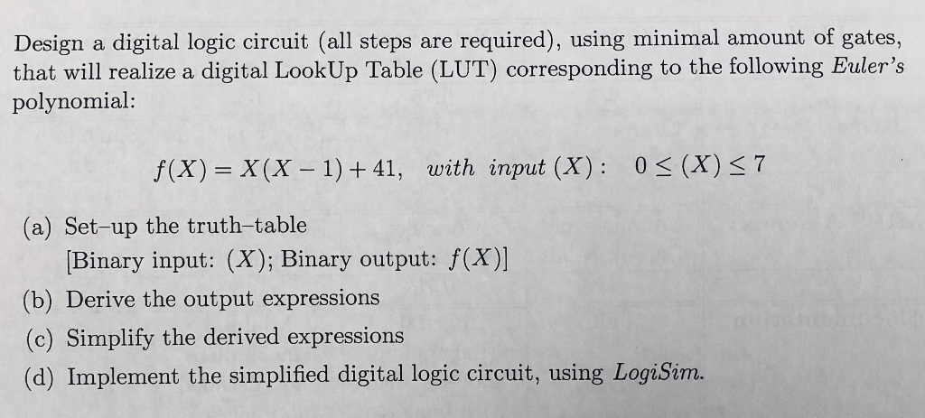
Design a digital logic circuit (all steps are required), using minimal amount of gates, that will realize a digital LookUp Table (LUT) corresponding to the following Euler’s polynomial: (x) X(X – 1) +41, with input (X): 0 s (X)s7 (a) Set-up the truth-table Binary input: (X); Binary output: f(X)] (b) Derive the output expressions (c) Simplify the derived expressions (d) Implement the simplified digital logic circuit, using LogiSim. Show transcribed image text Design a digital logic circuit (all steps are required), using minimal amount of gates, that will realize a digital LookUp Table (LUT) corresponding to the following Euler’s polynomial: (x) X(X – 1) +41, with input (X): 0 s (X)s7 (a) Set-up the truth-table Binary input: (X); Binary output: f(X)] (b) Derive the output expressions (c) Simplify the derived expressions (d) Implement the simplified digital logic circuit, using LogiSim.
Expert Answer
Answer to Design a digital logic circuit (USING LOGISIM), using minimal amount of gates that will realize a digital LookUp Table. … . . .
OR
