
[Solved]Design Plc Program Prepare Typical Vo Connection Diagram Ladder Logic Program Correctly Ex Q37210094
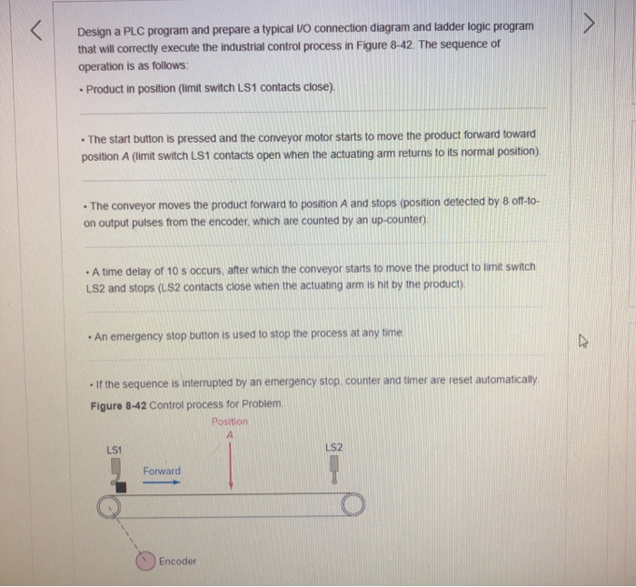 Design a PLC program and prepare a typical VO connection diagram and ladder logic program that will correctly execute the industrial control process in Figure 8-42. The sequence of operation is as follows: Product in position (limit switch LS1 contacts close). The start button is pressed and the conveyor motor starts to move the product forward toward position A (limit switch LS1 contacts open when the actuating arm returns to its normal position) . The conveyor moves the product forward to position A and stops (position detected by 8 off to- on output putses from the encoder wnich are counted by an up-counten) A time delay of 10 s occurs, after which the conveyor starts to move the product to limit switch LS2 and stops (uS2 contacts close when the actuating arm s hit by the product), An emergency stop button is used to stop the process at any time -if the sequence is interuptea by an emergency stop counter and tmer are reset automaticaly. Figure 8-42 Control process for Problem Position LS2 LS1 Forward Encoder Show transcribed image text Design a PLC program and prepare a typical VO connection diagram and ladder logic program that will correctly execute the industrial control process in Figure 8-42. The sequence of operation is as follows: Product in position (limit switch LS1 contacts close). The start button is pressed and the conveyor motor starts to move the product forward toward position A (limit switch LS1 contacts open when the actuating arm returns to its normal position) . The conveyor moves the product forward to position A and stops (position detected by 8 off to- on output putses from the encoder wnich are counted by an up-counten) A time delay of 10 s occurs, after which the conveyor starts to move the product to limit switch LS2 and stops (uS2 contacts close when the actuating arm s hit by the product), An emergency stop button is used to stop the process at any time -if the sequence is interuptea by an emergency stop counter and tmer are reset automaticaly. Figure 8-42 Control process for Problem Position LS2 LS1 Forward Encoder
Expert Answer
Answer to Design a PLC program and prepare a typical VO connection diagram and ladder logic program that will correctly execute th… . . .
OR
