
[solved]-Goal Part Design Hardwired Control Unit Simple Processor Asked Implement Gate Level Circui Q39064699
The goal of this part is to design a hardwired control unit fora simple processor:
You are asked to implement gate level circuit design of theprocessor that implements the following instruction set.
ONLY use AND, OR, NOT gates, and D-FLIP FLOP
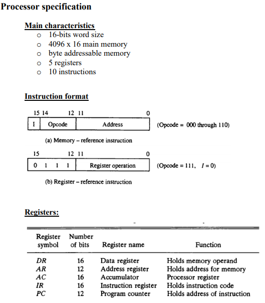
Processor specification Main characteristics o 16-bits word size o 4096 x 16 main memory o byte addressable memory o 5 registers o 10 instructions Instruction format 15 14 12 11 1 Opcode Address (Opcode = 000 through 110) 15 Oi (a) Memory-reference instruction 12 11 l Register operation (Opcode = 111, 1 = 0) (b) Register – reference instruction Registers: Register Number symbol of bits Register name Function DR AR Data register Address register Accumulator Instruction register Program counter Holds memory operand Holds address for memory Processor register Holds instruction code Holds address of instruction Computer instructions Hexadecimal code 1 – 0 1 = 1 Symbol Description xxx AND ADD LDA STA BUN BSA ISZ Oxxx 1xcx 2xoo 3xxx 4xxx Soox Axxx Вха Ceux Dxxx Exxx AND memory word to AC Add memory word to AC Load memory word to AC Store content of AC in memory Branch unconditionally Branch and save return address Increment and skip if zero ба CMA INC 7800 7200 7020 Clear AC Complement AC Increment AC Datapath Memory unit 4096 x 16 Address Write Read AR LD INR PC LD INR LD INR LD INR CLR Clock 16-bit common bus The control unit 15 14 13 12 X8 7 6 decoder 5 4 3 2 1 0 lopke -MemRd Mem Wr – ADD AND Com PassD ACLD ACINC ACCLR PCLD PCINC IRLD DRZero DRLD 35 decoder DRINC ARINC shit – Increment (INR) Clear (LR) Clock cor (SC) Instructions: • • You should implement gate level circuit designs of the control unit for this processor. You can use the same CAD tool that you used for part 1. You should use only the following gate level primitives: AND, OR, NOT gates and D-flip flop. Connect the IR register and the 3-bit counter to the control unit through the decoder, see above figure. Suppose that new instruction is already fetched to the IR register, and the IR contains 0x9000, show the value of all control signals (using CAD tool) Your solution should be documented, well-organized, modular and easy to study, you are required to explain briefly each component in the control unit. We were unable to transcribe this imageShow transcribed image text Processor specification Main characteristics o 16-bits word size o 4096 x 16 main memory o byte addressable memory o 5 registers o 10 instructions Instruction format 15 14 12 11 1 Opcode Address (Opcode = 000 through 110) 15 Oi (a) Memory-reference instruction 12 11 l Register operation (Opcode = 111, 1 = 0) (b) Register – reference instruction Registers: Register Number symbol of bits Register name Function DR AR Data register Address register Accumulator Instruction register Program counter Holds memory operand Holds address for memory Processor register Holds instruction code Holds address of instruction
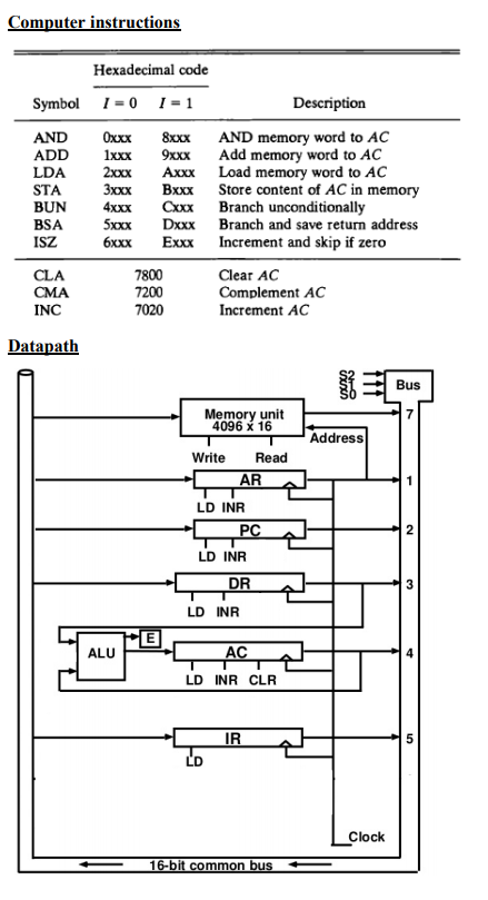
Computer instructions Hexadecimal code 1 – 0 1 = 1 Symbol Description xxx AND ADD LDA STA BUN BSA ISZ Oxxx 1xcx 2xoo 3xxx 4xxx Soox Axxx Вха Ceux Dxxx Exxx AND memory word to AC Add memory word to AC Load memory word to AC Store content of AC in memory Branch unconditionally Branch and save return address Increment and skip if zero ба CMA INC 7800 7200 7020 Clear AC Complement AC Increment AC Datapath Memory unit 4096 x 16 Address Write Read AR LD INR PC LD INR LD INR LD INR CLR Clock 16-bit common bus
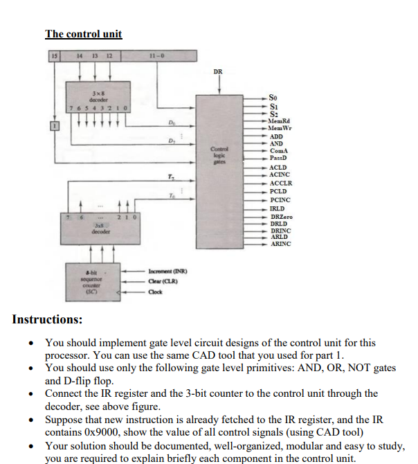
The control unit 15 14 13 12 X8 7 6 decoder 5 4 3 2 1 0 lopke -MemRd Mem Wr – ADD AND Com PassD ACLD ACINC ACCLR PCLD PCINC IRLD DRZero DRLD 35 decoder DRINC ARINC shit – Increment (INR) Clear (LR) Clock cor (SC) Instructions: • • You should implement gate level circuit designs of the control unit for this processor. You can use the same CAD tool that you used for part 1. You should use only the following gate level primitives: AND, OR, NOT gates and D-flip flop. Connect the IR register and the 3-bit counter to the control unit through the decoder, see above figure. Suppose that new instruction is already fetched to the IR register, and the IR contains 0x9000, show the value of all control signals (using CAD tool) Your solution should be documented, well-organized, modular and easy to study, you are required to explain briefly each component in the control unit.
Expert Answer
Answer to The goal of this part is to design a hardwired control unit for a simple processor: You are asked to implement gate leve… . . .
OR
